
Love-o-Meter
If you and your group have any questions, or get stuck as you work through this in-class exercise, please ask the instructor for assistance. Have fun!
-
If you haven’t already, please go to the TinkerCad website and create an account
Once you have the account created, go to Dashboard -> select Circuits on the left side panel -> select Create new Circuit
Materials needed (you might find it helpful to drag all the items into the workspace before you start putting them together):


- Arduino Uno R3
- Breadboard Small
- 3 LED Lights
- 1 Temperature Sensor
- 3 220-Ohm (or 220 Ω) Resistors with the following striping rom left to right: red, red, brown, gold
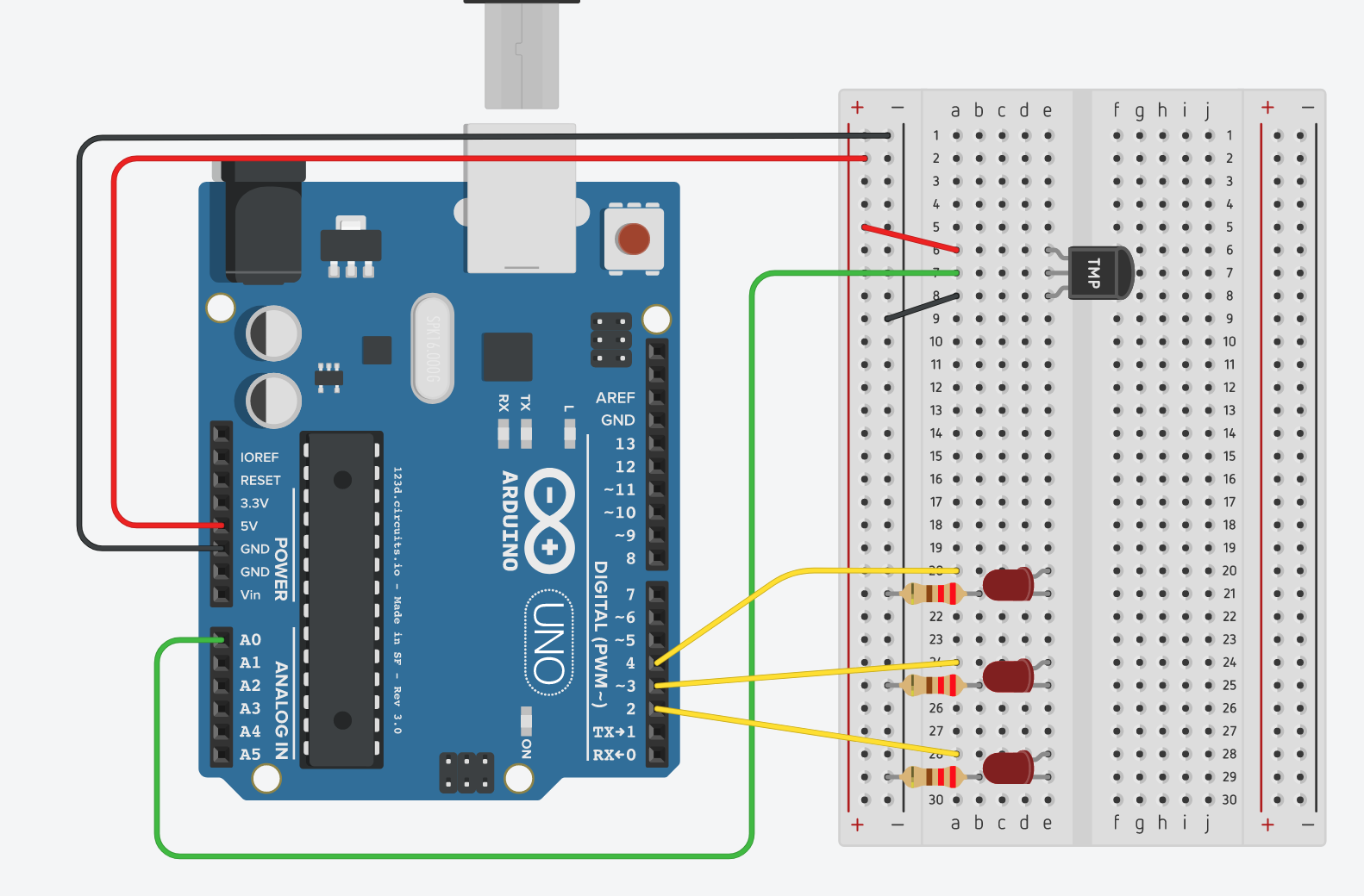
Attach as displayed in this diagram (note that the squiggly lines indicate the longer legs of the LEDs):
If desired, you can check out a simulated version of this Arduino project
-
TinkerCad would not produce the desired code by itself, so once everything is connected, go to the Code section, switch the option to Text and paste the following code (replacing the code that is already there):
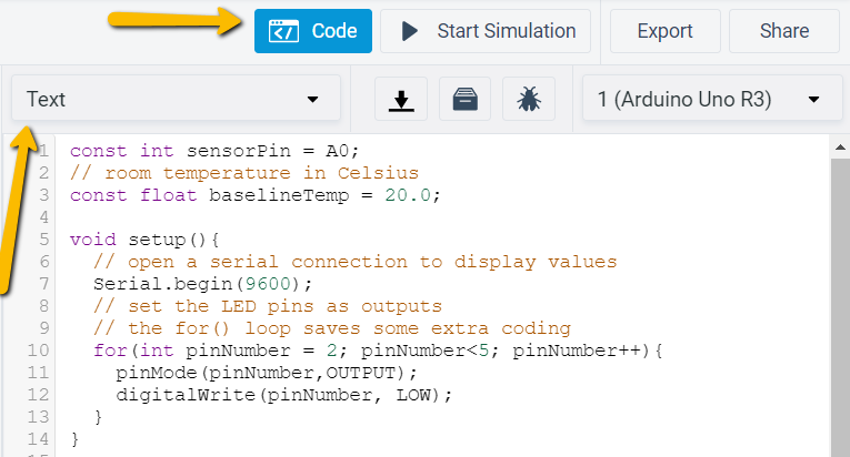
const int sensorPin = A0;
// room temperature in Celsius
const float baselineTemp = 20.0;
void setup(){
    // open a serial connection to display values
    Serial.begin(9600);
    // set the LED pins as outputs
    // the for() loop saves some extra coding
    for(int pinNumber = 2; pinNumber<5; pinNumber++){
        pinMode(pinNumber,OUTPUT);
        digitalWrite(pinNumber, LOW);
    }
}
void loop(){
    // read the value on AnalogIn pin 0
    // and store it in a variable
    int sensorVal = analogRead(sensorPin);

    // send the 10-bit sensor value out the serial port
    Serial.println("sensor Value: ");
    Serial.println(sensorVal);

    // convert the ADC reading to voltage
    float voltage = (sensorVal/1024.0) * 5.0;

    // Send the voltage level out the Serial port
    Serial.println(", Volts: ");
    Serial.println(voltage);

    // convert the voltage to temperature in degrees C
    // the sensor changes 10 mV per degree
    // the datasheet says there's a 500 mV offset
    // ((voltage - 500mV) times 100)
    Serial.println(", degrees C: ");
    float temperature = (voltage - .5) * 100;
    Serial.println(temperature);

    // if the current temperature is lower than the baseline
    // turn off all LEDs
    if(temperature < baselineTemp){
        digitalWrite(2, LOW);
        digitalWrite(3, LOW);
        digitalWrite(4, LOW);
    } // if the temperature rises 2-4 degrees, turn an LED on
    else if(temperature >= baselineTemp+2 && temperature < baselineTemp+4){
        digitalWrite(2, HIGH);
        digitalWrite(3, LOW);
        digitalWrite(4, LOW);
    } // if the temperature rises 4-6 degrees, turn a second LED on
    else if(temperature >= baselineTemp+4 && temperature < baselineTemp+6){
        digitalWrite(2, HIGH);
        digitalWrite(3, HIGH);
        digitalWrite(4, LOW);
    } // if the temperature rises more than 6 degrees, turn all LEDs on
    else if(temperature >= baselineTemp+6){
        digitalWrite(2, HIGH);
        digitalWrite(3, HIGH);
        digitalWrite(4, HIGH);
    }
    delay(100);
}

- Once the code is in, click Start Simulation, then click on the Temperature Sensor and move the temperature bar up and down and see the effect on the lights
