Light Theremin
If you and your group have any questions or get stuck as you work through this in-class exercise, please ask the instructor for assistance. Have fun!
-
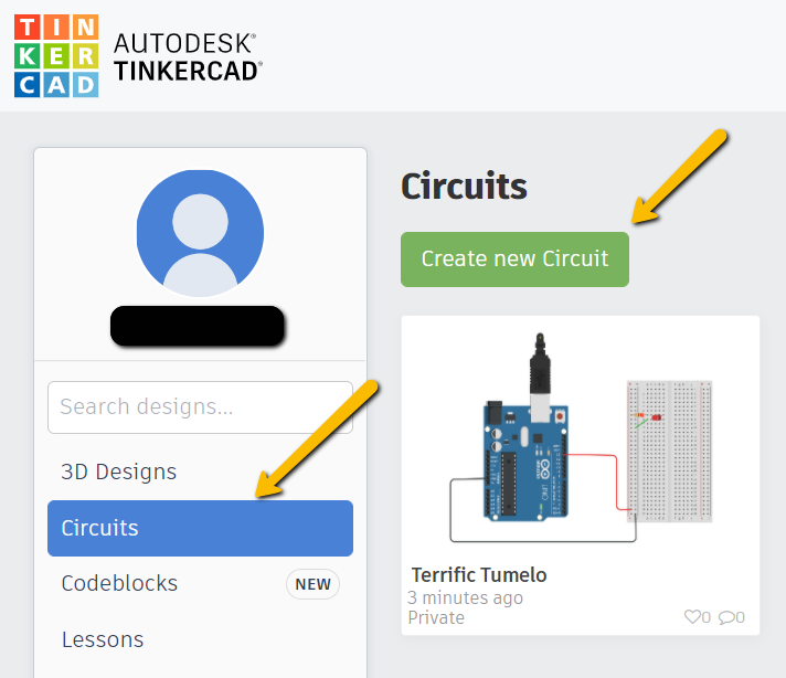
If you haven’t already, please go to the TinkerCad website and create an account
Once you have the account created, go to Dashboard -> select Circuits on the left side panel -> select Create new Circuit
Materials needed:


- 1 Piezo (this is basically a small speaker)
- 1 Photoresistor (this is a light sensor)
- 1 10k-ohm (or 10kΩ) Resistor with the following striping from left to right: brown, black, orange, gold
Connect as shown in this diagram (note: the Piezo legs are closer together than displayed here – just make sure the two adjacent wires in Column A are in the same row as the Piezo legs):
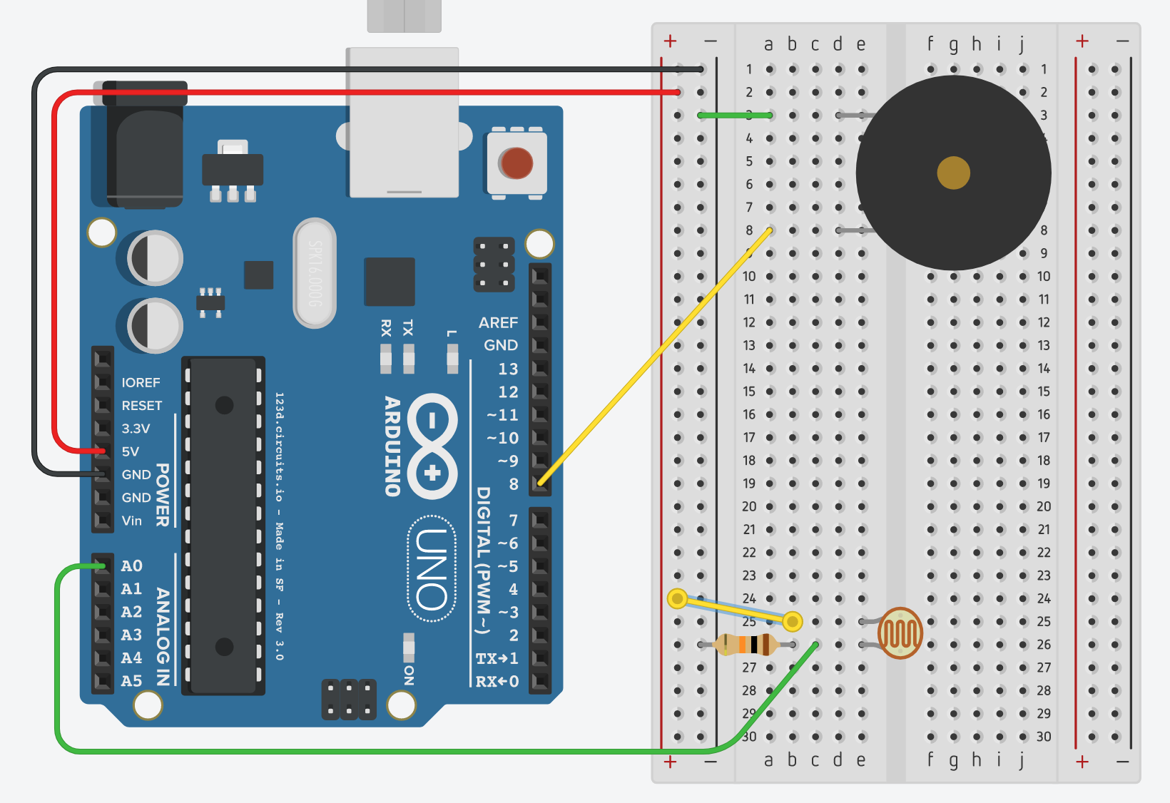
Note: you can check out a simulated version of this Arduino project
-
TinkerCad would not produce the desired code by itself, so once everything is connected, go to the Code section, switch the option to Text and paste the following code (replacing the code that is already there):
int sensorValue;
// variable to calibrate low value
int sensorLow = 1023;
// variable to calibrate high value
int sensorHigh = 0;
// LED pin
const int ledPin = 13;

void setup() {
    // Make the LED pin an output and turn it on
    pinMode(ledPin, OUTPUT);
    digitalWrite(ledPin, HIGH);
    // calibrate for the first five seconds after program runs
    while (millis() < 5000) {
        // save the maximum sensor value
        sensorValue = analogRead(A0);
        if (sensorValue > sensorHigh) {
            sensorHigh = sensorValue;
        }
        // save the minimum sensor value
        if (sensorValue < sensorLow) {
            sensorLow = sensorValue;
        }
    }
    //turn the LED off, signaling the end of the calibration
    digitalWrite(ledPin, LOW);
}

void loop() {
    //read the input from A0 and store it in a variable
    sensorValue=analogRead(A0);
    // map the sensor values to a wide range of pitches
    int pitch=map(sensorValue, sensorLow, sensorHigh, 50, 4000);
    // play the tone for 20 ms on pin 8
    tone(8, pitch, 20);
    // wait for 10ms
    delay(10);
}

- Once the code is in, click Start Simulation, then click on the Photoresistor and move the light bar down and wait for the sound effect. NOTE: There is a 5 second initialization phase where the ambient light level is recorded (Note: the timer at the top for the countdown, which will take more than 5 seconds because it’s keeping track of “computer” time). After that, move the photoresistor bar up and down to make some crazy Theremin sounds! Enjoy!
