Lucky 8-Ball
If you and your group have any questions or get stuck as you work through this in-class exercise, please ask the instructor for assistance. Have fun!
-
If you haven’t already, please go to the Arduino website and download the “Arduino IDE” for either Windows or Mac, and then install the software on your computer.
Materials needed:
- 1 LCD Screen (see below)
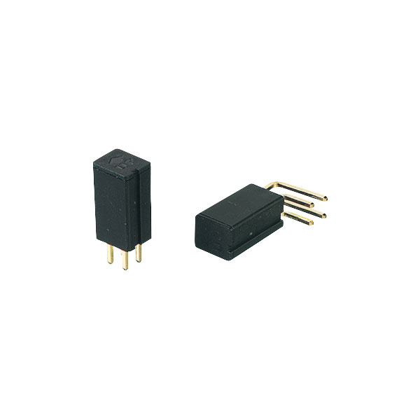
- 1 Tilt Switch (4 prongs)
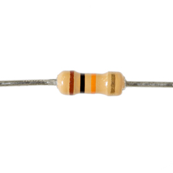
- 1 10k-ohm Resistor with the following striping in order: brown, black, orange, gold
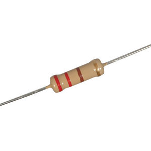
- 1 220-ohm Resistor with the following striping in order: red, red, brown, gold
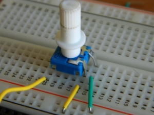
- 1 Potentiometer
- 1 Long Red Wire
- 1 Long Black Wire
- See Below for the remaining wires and their placement
-
Connect the black wire to the GND pin on the Arduino and then the “-” pin on the breadboard.
-
Connect the red wire to the 5V pin on the Arduino and then the “+” pin on the breadboard.
-
Connect all the other wires as can be seen in the diagram below.
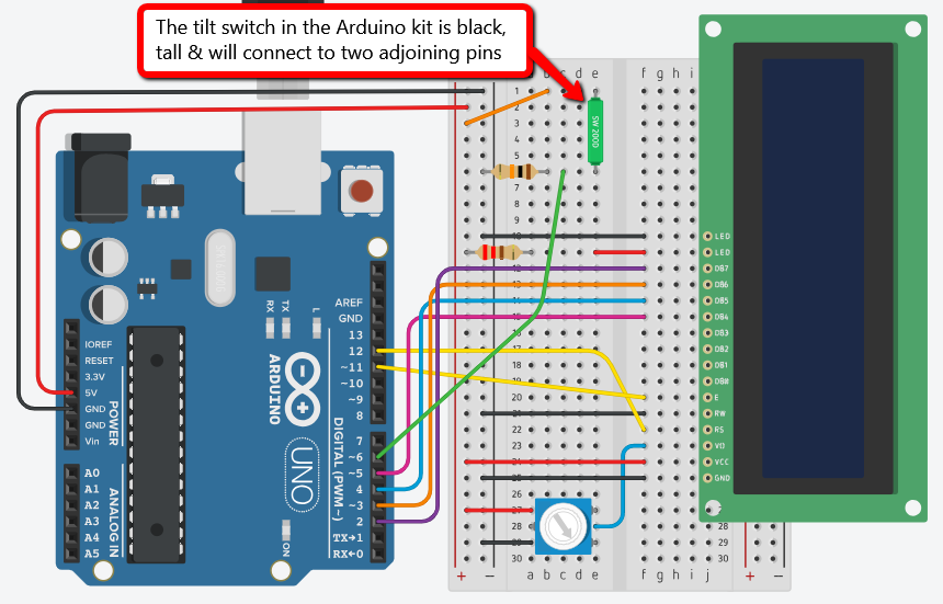
Note: you can check out a simulated version of this Arduino project.
The image of the tilt sensor/switch shown in the breadboard schematic is different from the actual 4-prong tilt switch/sensor we are using. The actual 4-prong tilt switch/sensor we are using and its connection are shown in this photo:
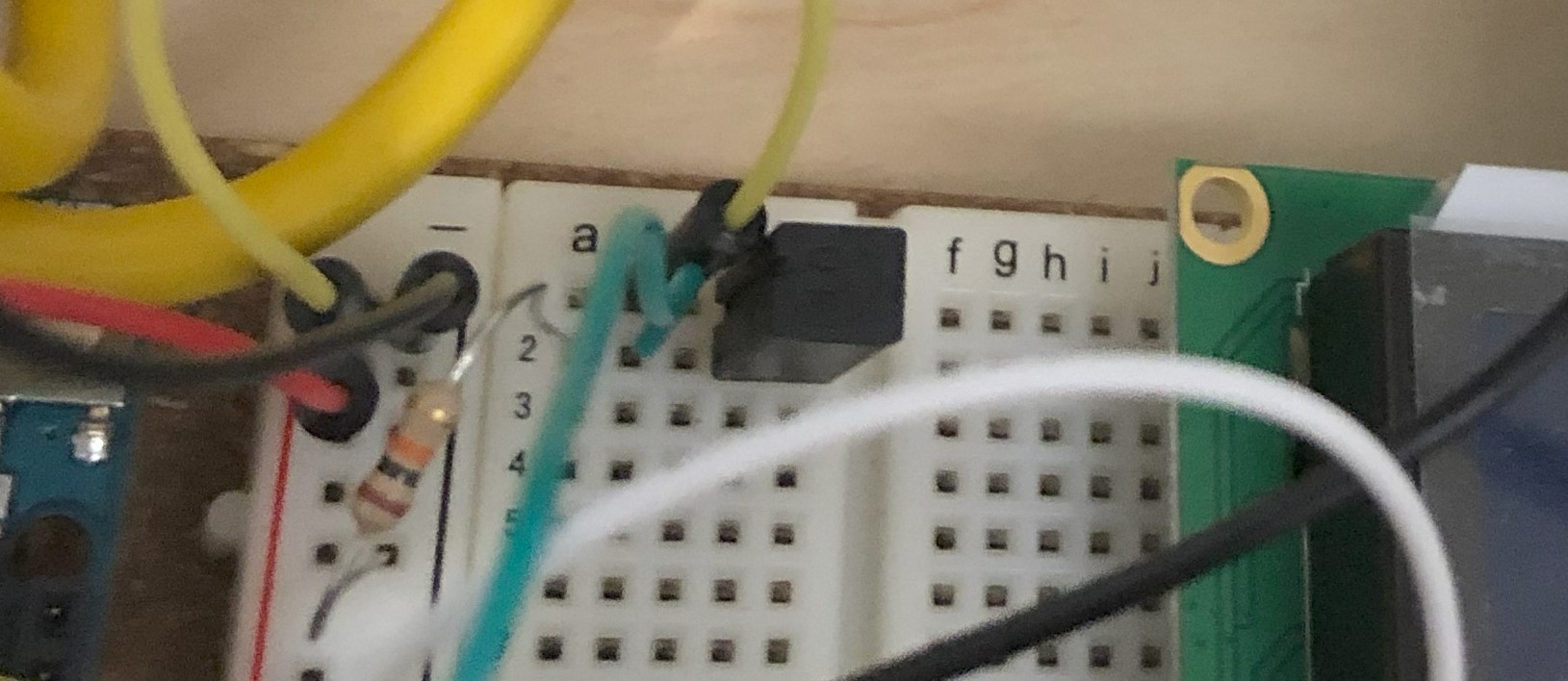
Detailed explanation can be referred to the link: https://arduino.stackexchange.com/questions/92596/correctly-connecting-a-four-pin-tilt-sensor-to-a-breadboard-before-going-live. We recommend connecting with a 10 K ohm pull-up resistor, which is a safer way for the circuit. Datasheet for RBS040100 tilt switch/sensor can be found here: https://docs.rs-online.com/05f0/0900766b8066b85f.pdf
-
Using the provided USB cable plug your Arduino into your computer.
-
Launch the arduino software.
-
Go to the top menu of the Arduino Program and select: File -> Examples -> 10.StarterKit_BasicKit -> p11_CrystalBall
-
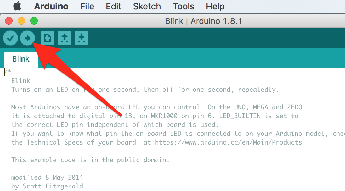
Upload the Crystal Ball code to your Arduino by pressing the Upload button.
For debugging, you could add a line within the setup() function: Serial.begin(9600); // Opens serial port at 9600 bps Then add other lines to print out the information to track the execution of the program: Serial.print(“Any debug messages!”) // Change “Any debug messages” for different lines Then open the serial monitor window from the menu of the IDE: Tools->Serial monitor Download the code to the Arduino board. If the debug messages are shown in the serial monitor, the programming part should be good.
-
Twist the potentiometer until you see words appear on the screen. Once the code is uploaded and running, you trigger your Lucky 8-Ball by moving its base gently up and down to trigger the tilt sensor. The tilt sensor and the potentiometer can sometimes pop out, so you might have to keep a finger on the sensor as you shake it!
If there is nothing shown on the screen or even if the screen is off, check the wiring on the breadboard. If the wiring on the breadboard is correct, at least you will see that the screen is on. When adjusting the potentiometer, the background light intensity for the LCD will change.
After all the signal pins and power/GND pins to the LCD are checked, it will likely be working. But if the LCD is not working properly yet, check the voltage for the power rails on the breadboard and the pins of the LCD with a multimeter, also double-check the voltage pins on the Arduino board. Make sure that you are using 5V rather than 3.3V. You could also compare the wiring of our demo board with yours for a fast double-check. Change the LCD with another one if necessary.
When all of these are done, you will probably get the LCD to display the words!
- You should probably customize the responses of your lucky 8-Ball by going into the Arduino software and scrolling down to almost the bottom of the code for the project, and look for lcd.print(“Yes”);, and lcd.print(“Most likely”);. Go ahead and change any or all of the 8 different responses that your Lucky 8-Ball gives out (just remember that your responses still have to fit on the LCD screen). Upload your revised code, and you’re off to the races. Enjoy!