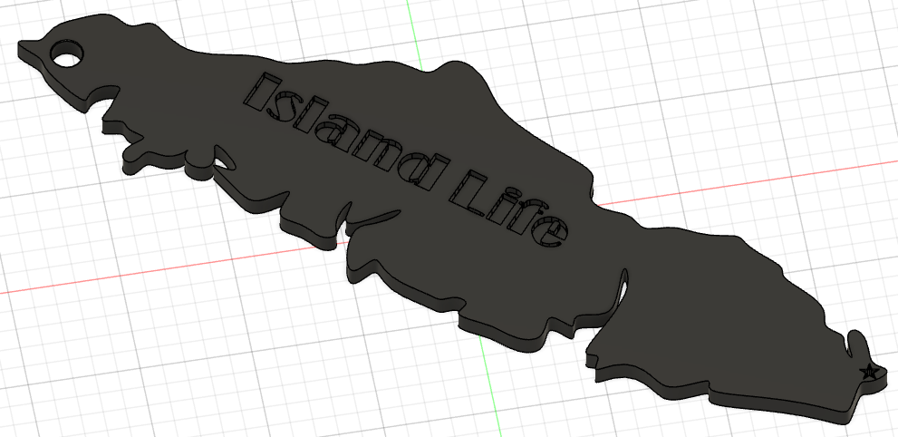
Create a Part from a Reference Image
If you or your group have any questions or get stuck as you work through this in-class exercise, please ask the instructor for assistance. Have fun!
- Download and install Fusion 360.
- Check your laptop specs to ensure it’s able to run Fusion 360. System requirements are listed here: https://autode.sk/2qg8ryB
- Follow this link: https://autode.sk/3DW7TRB to make an Autodesk account and download Fusion 360
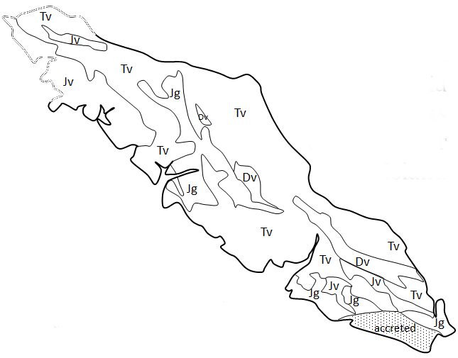
- Download an image file:
- Download the Vancouver Island image file by clicking here
- Launch Fusion 360 and get familiar with how to move around.
- Hold down the mouse wheel and drag to move.
- Press the shift key while holding down the mouse wheel to rotate.
- Scroll the mouse wheel to zoom in and out.
- Click to select.
- Press Esc to clear a selection.
- Import the image into Fusion 360:
- Open Fusion 360, it will automatically make a new part.
- Click on the Insert drop-down menu on the top navigation bar and select Canvas. Click insert from my computer and select the image file you downloaded.
- Click the plane you want to put your image on (the top plane is recommended), then click and drag the box on top of the image to resize. For more exact sizing, type a scale factor of 10 into the scale plane box. Click ok.
- Trace the image:
- Make a new sketch. Click the sketch icon
 then click on the same plane as your image.
 - Click on the Fit Point Spline tool

- Click along the edges of the canvas to trace the outline. Place as many points as you like - more points will give you a more accurate outline, but will take longer. Click esc to exit the spline tool.
- Click and drag the black dots to adjust the position of each spline point, click and drag the ends of the green line to adjust the curve.
- Once you’re happy with your outline, Click the Solid tab on the top left and click on the Extrude feature
 . Select your outline and set 5 mm as the distance.
- Make a new sketch. Click the sketch icon
-
Add a star marker:
- Hide your reference image to make sketching easier. On the left sidebar, click the eye icon next to Canvases. Note: click the eye again if you want to show the image.
- Click the Create Sketch feature to start a new sketch. Select the top plane.
- Select Polygon from the create drop-down, then click on Circumscribed Polygon. Click where you want the center of the polygon to go, then change the number of sides to 5. Click anywhere to place your polygon, then hit esc.
- Use the dimension
 tool to set one of the sides to 2 mm. click and drag the center of the star to ensure it isn’t too close to the edge.
 - Select the line tool
 under the create drop-down, then draw a star inside the pentagon.
 - Use the trim tool
 to remove extra lines. Hold the Shift key and click on each side of the pentagon, then Click the construction button
  next to linetype in the sketch palette. The outside of the pentagon should now appear as dotted lines.
Note: construction lines are useful references for a sketch, and will be ignored when extruding. - Click the Solid tab on the top left and click on the Extrude feature . Click inside your star sketch to select it, then choose Operation as Cut, and Extent Type as All. Click OK.
- OPTIONAL: Add extra features
- Cut a keychain hole
- Add text or other features to the top of the part
- Export as stl file:
- Save by clicking the Save button on the top left of the screen. Click on File, then Export. Change the Type to the .stl file format and choose a location to save it, and select Export. It may take a couple of minutes to export.
Congratulations! You now have a printable model of Vancouver Island!