Getting Started with Fusion 360
Fusion 360 has A LOT of features. Here’s a quick guide of tools and features to help get you started on your first project!
- Moving around
- Hold down the mouse wheel and drag to move.
- Press the shift key while holding down the mouse wheel to rotate.
- Scroll the mouse wheel to zoom in and out.
- Click to select.
- Hold down the mouse wheel and drag to move.
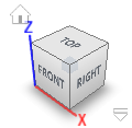
- Changing the view of your workspace
- In the top right corner of the workspace there is a cube. Click on different faces, edges, or corners to quickly see your design from different angles.
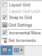
- At the bottom of the screen there’s a toolbar. Click the Grids and Snaps icon to change these features.
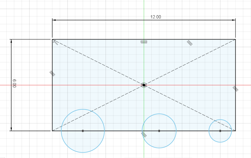
- Sketch dimensioning
- Sketch lines will show up as blue or black, depending on how they’re dimensioned. Black lines are fully defined, meaning the line’s length and position has been completely described by dimensions. Blue lines are under-defined, meaning at least one dimension is missing. It’s best to have fully defined lines because they are controlled and cannot be accidentally moved.
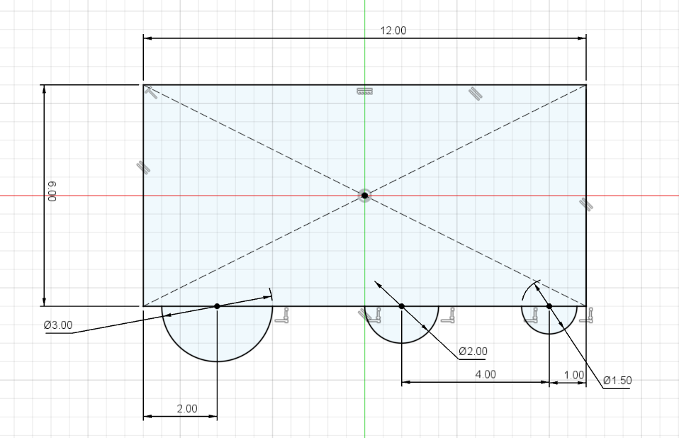
- Dimension sketches such that they’re easy to read. They will likely need to be edited later.
- The Trim tool
 can be used to remove excess sketch lines. This keeps the sketch clean and makes extruding or revolving it easier.
- Sketch lines will show up as blue or black, depending on how they’re dimensioned. Black lines are fully defined, meaning the line’s length and position has been completely described by dimensions. Blue lines are under-defined, meaning at least one dimension is missing. It’s best to have fully defined lines because they are controlled and cannot be accidentally moved.
- Common features
- Extrude
 is used for moving a sketch in a straight line to create a 3D feature.
 - Revolve
 is used for rotating a sketch around an axis to create a 3D feature. Make round parts using a revolve instead of a series of extrudes. Then you only need to edit one sketch.
 - Hole
 is a quick way to make several of the same hole type such as a clearance or threaded hole for a screw.
 - Fillet/Chamfer

 are tools used to modify the edges of a part. These features should only be used at the very end of designing a part. Otherwise, the wrong edges may be selected for dimensioning or errors may be caused.

- Extrude
- Measuring
- The Measure tool lets you quickly view a dimension without going into a sketch. Above the Inspect menu, click on the Measure
 tool.
tool. - Click on a surface, edge, or point. Geometric properties relating to that feature will appear.
- Click on a second surface, edge, or point. The distances between the two features will appear.
- The Measure tool lets you quickly view a dimension without going into a sketch. Above the Inspect menu, click on the Measure
- Cross-section view
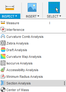
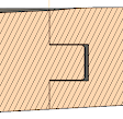
- Viewing an object through the middle can be useful (e.g. in activity 5, we will make interlocking parts). Viewing a cross-section is useful to ensure there is no interference between features.
- Click on the Inspect drop-down menu. Click on Section Analysis. Click on a plane that is parallel to the plane you want to view your object, then drag the cross-section plane to the area you want. Click OK.
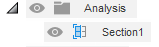
- To turn the feature on and off, find the Analysis folder in the top left Browser. Click the eye next to the Section to turn its visibility on or off.
- Renaming features
- The design Timeline is at the bottom left of your screen and shows all changes made to your design. It can quickly get messy, especially when designing parts with a lot of features. Renaming features helps to remind you of the feature’s purpose.
- Right-click on a feature, then click Rename. Type an appropriate name and hit the Enter key.
- Now when you hover your mouse over the feature in the Timeline, you will be able to see your custom name.
- The design Timeline is at the bottom left of your screen and shows all changes made to your design. It can quickly get messy, especially when designing parts with a lot of features. Renaming features helps to remind you of the feature’s purpose.
- Editing features
- A feature or sketch can be edited by right-clicking on it from the Timeline, then clicking Edit Feature or Edit Sketch. Dimensions and other parameters can then be changed.
- After you make a part, you will almost certainly need to go back and edit various aspects of it. Often, editing time will exceed initial designing time. Consider the following questions when doing the initial design:
- What dimensions are the most likely to be modified?
- If the outer dimensions of the part change, how do I want the other features to move with respect to the body?
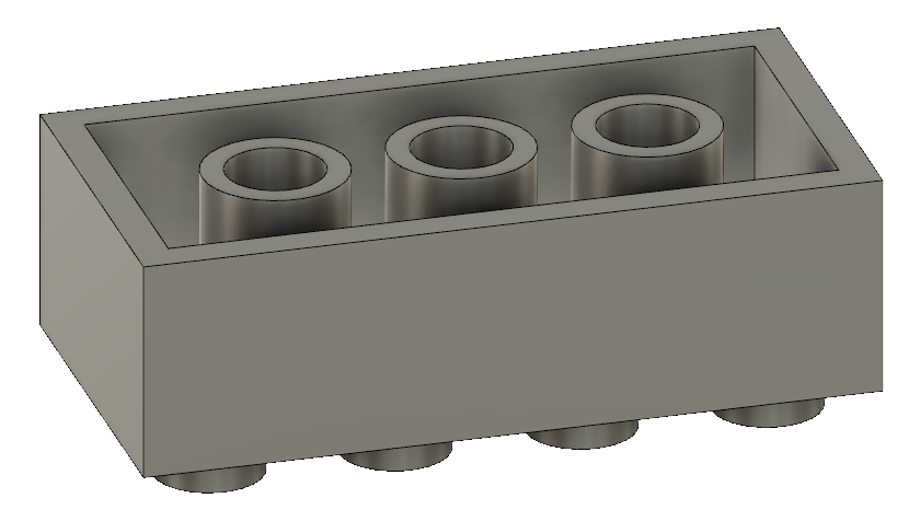
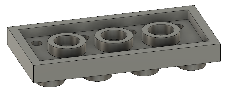
- How should I setup a feature such that it changes (or doesn’t) when other features change? (e.g. in the Lego activity, it only takes one edit to change the Lego into a “short” Lego because one extrude depends on the length of another extrude).
- What dimensions are the most likely to be modified?
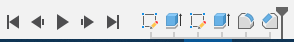
- Sketches and features can be inserted into the middle of the Timeline by dragging this icon
 backwards (left) in the Timeline. Continue with sketching and feature creation as usual. Then move it back to the end of the Timeline. This is desirable when the part has been “finished” with fillets and chamfers but it turns out another feature needs to be added.
- A feature or sketch can be edited by right-clicking on it from the Timeline, then clicking Edit Feature or Edit Sketch. Dimensions and other parameters can then be changed.