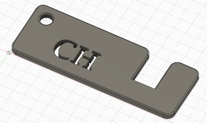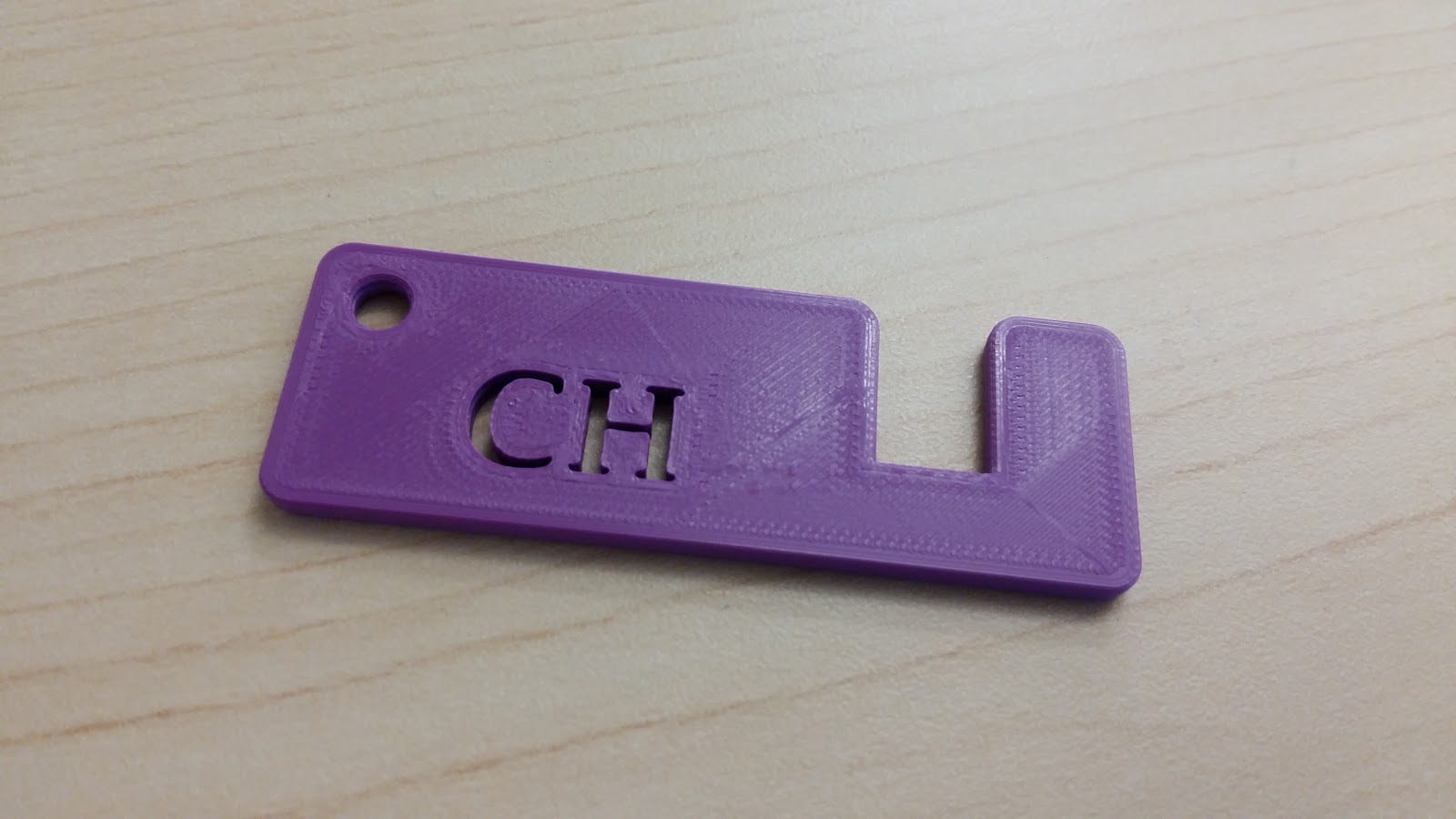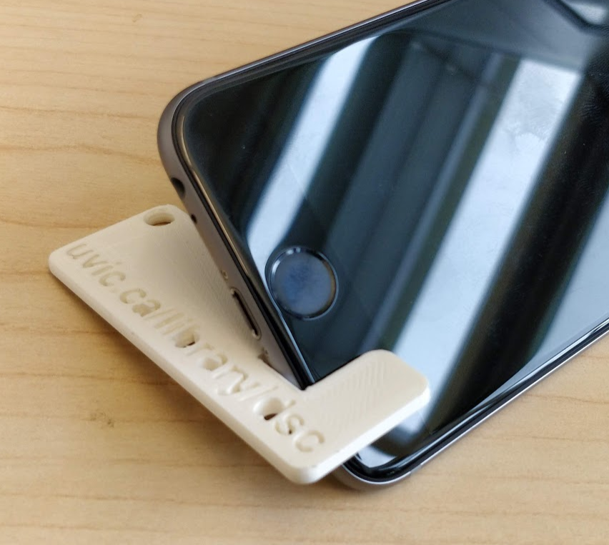
Design a Phone Stand
If you or your group have any questions or get stuck as you work through this in-class exercise, please ask the instructor for assistance. Have fun!
- Download & install Fusion 360:
- Check your laptop specs to ensure it can run Fusion 360: https://autode.sk/2qg8ryB
- Follow this link to make an Autodesk account and download Fusion 360: https://autode.sk/3DW7TRB
- Launch Fusion 360 and get familiar with how to move around:
- Hold down the mouse wheel and drag to move.
- Press the shift key while holding down the mouse wheel to rotate.
- Scroll the mouse wheel to zoom in and out.
- Click to select.
- Press Esc to clear a selection
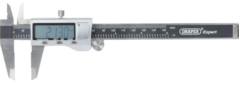
- Measure the width of your phone:
- Ask the instructor for a caliper tool so that you can measure the width of your cell phone.
- Write down or record the width of your cell phone out to two decimal places
- Now add 0.5 to the width of your phone and write it down or record it (e.g. if my phone was 8.50mm then I’d write 9.00mm)
- Create the basic shape of the phone stand:
- Start a new sketch by clicking the Create Sketch icon
 . It will prompt you to select a plane. A good practice is to select the plane from which the object would be viewed in real life. In this case, the top plane or horizontal plane is desired because that is how the object will be 3D printed.
- Select the 2-Point Rectangle tool
 . Click on the origin in the middle of the screen, then click somewhere above and to the right. Click the Esc key to exit the 2-Point Rectangle tool.
 - Try moving the sides of the rectangle around by selecting and dragging the blue edges of the square. The bottom and left sides can’t be moved because they’re defined by the origin. The top and right sides can be moved.
- Select the Sketch Dimension tool
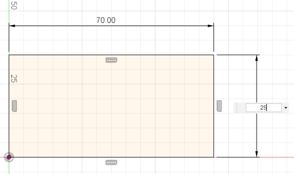
 . Click on the top line, move your mouse slightly above the line and click again. Enter 70 mm as the dimension. Repeat with the right line, but enter 25 mm.
 - Notice that all sides of the rectangle are black. This means the sketch is fully defined.
- Click on the SOLID tab at the top of the screen. Click on the Extrude feature
 . It will automatically select the interior area of the rectangle to extrude. Enter 2 mm as the thickness. Then click OK in the Extrude pop-up box.
 - Try rotating the part to view it in 3D by holding down the shift key and the mouse wheel.
- Start a new sketch by clicking the Create Sketch icon
-
Cut out a phone slot and keychain hole:
- Click on the top face of the object then click the Create Sketch tool
 .
. - Click on the 2-Point Rectangle tool. Click on the top line of the rectangle to constrain the first point of the rectangle to it and click lower and to the right of the first point.
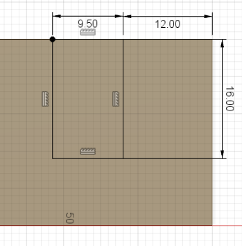
- Click on the Sketch Dimension tool. Click on the top line of the new rectangle, enter the value you calculated in step 3c. Click the right line, enter 16 mm. Now hold down your shift button & click the right side of the new rectangle and the right side of the old rectangle and enter 12 mm. Notice the rectangle is now fully defined and in the correct location.
-
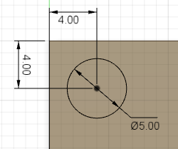
Click on the Center Diameter Circle tool
 . Click on the part near the top left corner. Click again to create a circle.
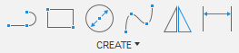
-
Click on the Sketch Dimension tool. Click on the circle and enter 5 mm. Click on the center of the circle and then click on the left line of the rectangle, enter 4 mm. Click on the center of the circle and then click on the top line of the rectangle, enter 4 mm.
- Click on the Create drop-down menu. Select Text from the drop-down menu. Click at an open point near the bottom right of the large rectangle & then in the open space on the top left (see below). Enter your desired parameters into the Text pop-up box. You may need to use the Flip commands to change the orientation of the text. You can drag the blue handle around to move your text. Note: 3D printers do better with bold text with minimal holes.
- Right-click on the text. Click Explode Text. Now your text should appear as lines.
- Click the SOLID menu tab. Click on Extrude
 . Select the faces to extrude (circle, rectangle, and text features). Rotate the view of the part so it’s in 3D. In the Extrude pop-up box change the Extent to All and click Flip. The Operation should be Cut. Click OK.
- Click on the top face of the object then click the Create Sketch tool
- Fillet and chamfer edges. Note: Always leave fillets and chamfers until after your design is completed.
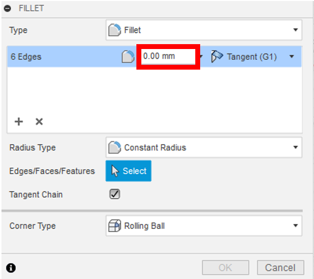
- Click on the Fillet tool on the top menu
 . Click on the 6 outside vertical corner edges of the rectangle in turn and change the fillet radius to 3 mm for all of them.
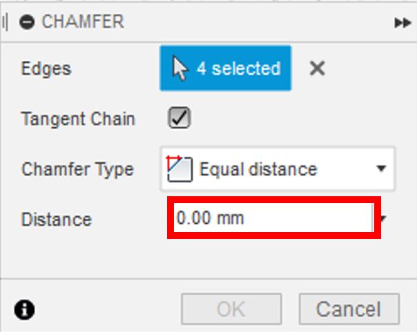
- Click on the Modify drop-down menu. Click on Chamfer. Click on the top edge of the hole and the top edge for the outside profile. Rotate around the keychain and select the same edges on the bottom. Enter a Distance of 0.5 mm, and press Enter.
- Click on the Fillet tool on the top menu
-
Save by clicking the Save button on the top left of the screen. Click on File, then Export. Change the Type to the .stl file format and choose a location to save it, and select Export. It may take a couple of minutes to export.
Congratulations! You can now 3D print your phone holder!