
Create a Lego Brick
If you or your group have any questions or get stuck as you work through this in-class exercise, please ask the instructor for assistance. Have fun!
- Download and install Fusion 360:
- Check your laptop specs to ensure it’s able to run Fusion 360. System requirements are listed here: https://autode.sk/2qg8ryB
- Follow this link: https://autode.sk/3DW7TRB to make an Autodesk account and download Fusion 360.
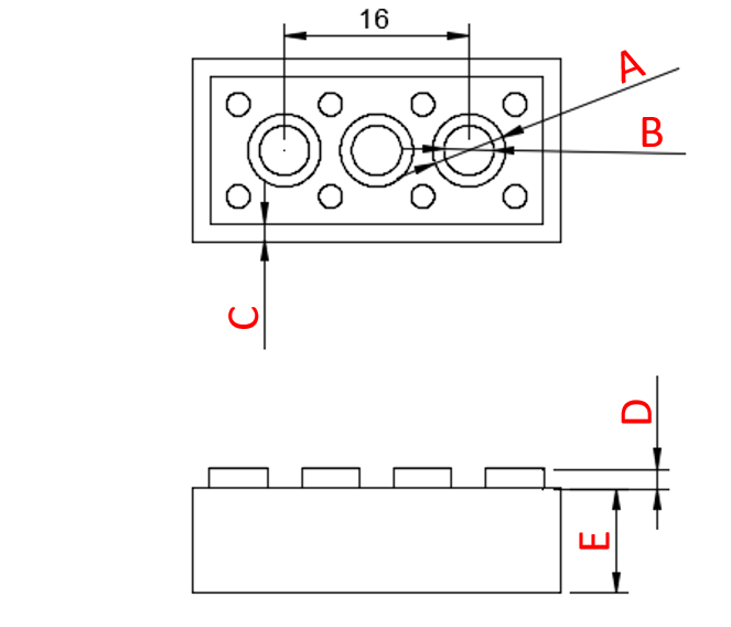
- Measure a Lego brick. Record the values to two decimal places. If you don’t have a lego brick, here are the dimensions you’ll need:
- A: 6.314 mm
- B: 5.314 mm
- C: 1.49 mm
- D: 1.7 mm
- E: 9.6 mm
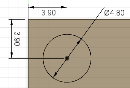
- F: 5.0 mm
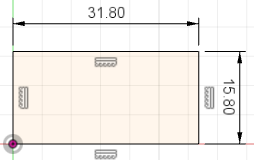
- G: 31.8 mm
- H: 15.8 mm
- Create a new part:
- Open Fusion 360.
- Click on your name icon
 in the top-right of the screen, then click on Preferences.
 - Select Design under General from the left side of the preferences window. Ensure Auto project geometry on the active sketch plane has a checkmark next to it. Click OK.
- To start a new design, click + on the top right, OR click File in the top-left, then New Design.
- Make the main body:
- Select the Create Sketch feature
 . Select the Top plane.
 - Select the 2-Point Rectangle tool. Click on the origin, then click somewhere above and to the right. Click the Esc key to exit the 2-Point Rectangle tool.
- Select the Sketch Dimension tool
 . Click on the top line, move your mouse slightly above the line and click again. Enter your measured “G” as the dimension. Repeat with the right line, but enter “H”.
 - Click over to the Solid tab on the top menu, and click on the Extrude feature
 . It will automatically select the interior area of the rectangle to extrude. Enter “E” as the thickness. Then click OK in the Extrude pop-up box.
- Select the Create Sketch feature
- Sketch a connector:
- Click on the top surface of the brick. Select the Create Sketch button on the top menu.
- Click on the Center Diameter Circle tool
 . Click near the top left corner of the big rectangle. Click again to create a circle.
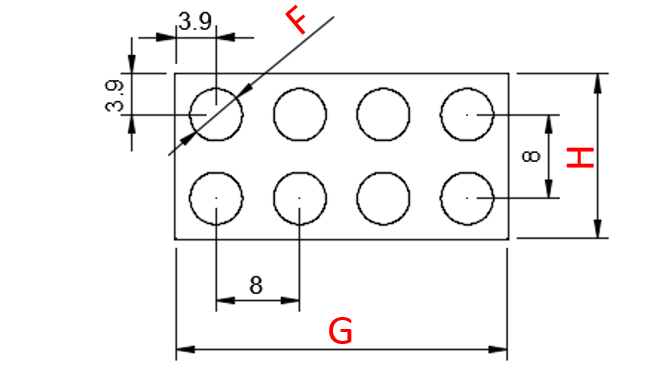
 - Click on the Sketch Dimension tool. Click on the circle and enter the “F” value. Click on the center of the circle and then on the left line of the rectangle, enter 3.9 mm. Click on the center of the circle and then on the top line of the rectangle, enter 3.9 mm. Click the Esc key to exit the tool.
- Click on the top surface of the brick. Select the Create Sketch button on the top menu.
- Add connectors with the Pattern tool:
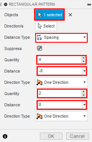
- Click on the sketch tab then click on the Create drop-down menu and select the Rectangular Pattern tool.
 . Note: there are two rectangular pattern tools, one in the sketch tab and one in the solid tab. Make sure you’re using the correct (sketch) tool!
 - Click on the circle. Change the following to match the diagram to the right: Distance Type, Quantities, and Distances. Ensure the Distance Type is Spacing. Click OK.
- Click the Solid tab button, then on the Extrude feature. Select the interior area of all the circles. Enter the “D” value as the thickness. Then click OK in the Extrude pop-up box.
- Click on the sketch tab then click on the Create drop-down menu and select the Rectangular Pattern tool.
- Hollow it out:
- Select the Shell feature
 .
. - Select the bottom of the Lego brick. Enter “C” as the Inside Thickness. Click OK.
- Select the Shell feature
- Add cylinders to bottom:
- Click on the bottom inside face. Click Create Sketch.
- In the Sketch Palette, on the far right, click the Construction icon
 . Then select Line
  from the sketch tools on the top menu. Click the center of the top-left circle, then click the center of the circle diagonal to it. Use the Esc key to exit the Line tool.
 - Click on the Center Diameter Circle tool. Hover over the middle of the line until a blue triangle appears. Click to place the center of a circle in the middle of the line, click again to make a circle. Repeat to make a smaller circle inside the first.
-
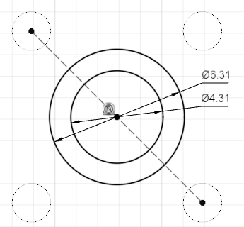
Click on the Sketch Dimension tool. Click on one circle and enter “A”. Click on the other and enter “B”.
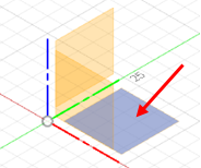
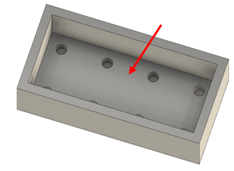
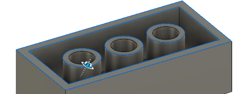
- Click over to the Solid tab. Click on the Extrude feature. Select the area between the two circles. Change the Extent to To Object. Select the space between the two outer rectangles (where the red arrow is pointing) as the Object. Then click OK in the Extrude pop-up box.
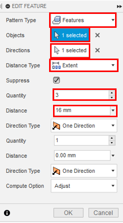
- Click on the Create drop-down menu. Click on Pattern to show a second menu. Select the Rectangular Pattern. Change the Pattern Type to Features. Select the newly-created cylinder. Click on the arrow next to Directions. Click on the red axis near the corner of the part. Enter 16 mm as the Distance. Ensure Quantity is 3. Click OK.
- Click on the bottom inside face. Click Create Sketch.
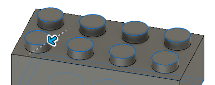
- Chamfer. Add a small chamfer to specific edges to make 3D printing and assembly easier:
- Click on the Modify drop-down menu and select the Chamfer tool
 . Select all the edges highlighted in blue shown in the pictures. Enter 0.25 mm as the Distance. Click OK.
- Click on the Modify drop-down menu and select the Chamfer tool
-
Save using the save icon on the top left of the screen. Click on File, then Export. Change the Type to the .stl file format and choose a location to save it. It may take a couple of minutes to export. Congratulations! You can now 3D print a Lego!
- OPTIONAL: Optimize your lego piece for 3D printing:
- Chamfer circle pieces on the bottom of the lego piece. This makes it easier for the studs at the top of one brick to be guided into the bottom of another without having the studs catch on the edges.
- Fillet internal corners underneath the lego piece. This makes it easier to print without supports since the eventual overhang of the top of the brick will be printed over a smaller distance if the internal walls have recently begun to slope inwards.